Electricity and Magnetism
|
5A10.10 |
ELECTROSTATICS |
|
|
Producing Static Charge |
||
Rods and Fur |
||
|
|
||
|
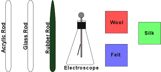
Rub the wool felt cloth on the PVC rod to produce negative charge on the rod. Rub the cellophane on the acrylic rod to produce positive charge on the rod. |
||
|
5A20.10 |
ELECTROSTATICS |
|
|
Coulomb's Law |
||
Rods and Pivot |
||
|
|
||
|
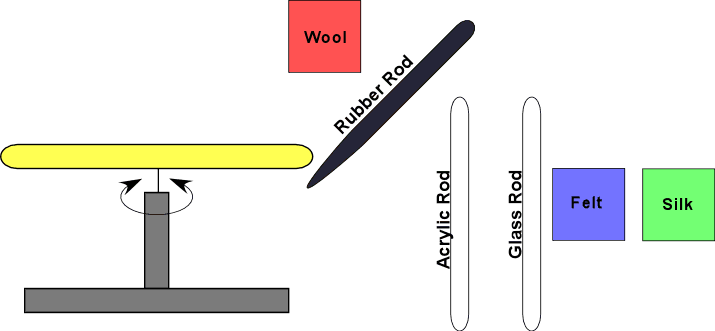
Rub both ends of a rod and center it on the pivot. Rub the PVC rod (negative charge) with the felt or the acrylic rod (positive charge) with the cellophane. Rub one end of a second rod and hold its charged end near the end of the rod on the pivot. |
||
|
5A22.25 |
ELECTROSTATICS |
|
|
Electrostatic Meters |
||
Soft Drink Can Electroscope |
||
|
|
||
|
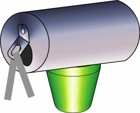
The tab of the soft drink can supports the electroscope leaves in this simple version. |
||
|
5A40.10 |
ELECTROSTATICS |
|
|
Induced Charge |
||
Charging by Induction |
||
|
|
||
|
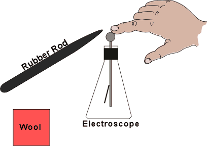
Charging by induction with an electroscope for a charge indicator. |
||
|
5A40.20 |
ELECTROSTATICS |
|
|
Induced Charge |
||
Charge Propelled Cylinder |
||
|
|
||
|
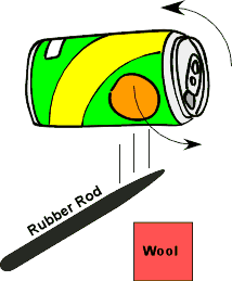
Set an empty soda can on the table so the open end faces the students. Pull the can forward with induced charge. Switch to the oppositely charged rod and repeat. |
||
|
5A50.30 |
ELECTROSTATICS |
|
|
Electrostatic Machines |
||
Van de Graaff Generator |
||
|
|
||
|
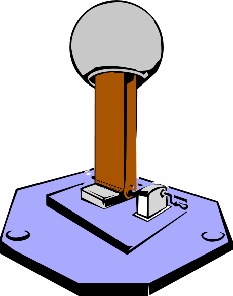
Have student stand on platform and place hand on top of VDG. Do not remove hand from the surface. Turn on the VDG and observe their hair. Turn off the VDG. Use grounding wire attached to base of generator to discharge the sphere, then allow student to withdraw hand. Place various equipment items in kit one at a time on top on the VDG and turn it on. |
||
|
5B10.10 |
ELECTRIC FIELDS AND POTENTIAL |
||
|
Electric Field |
|||
Hair on End |
|||
|
|
|||
|
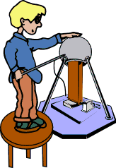
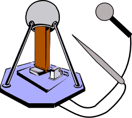
Remove pointed metal items such as keys and microphones. Stand on the insulated stool. With the variable control fully counter-clockwise, turn the power on. Hold the pointed probe against the sphere while turning up the motor. Place your other hand on the sphere before removing the probe. Do not remove your hand and stay away from anything metal. Allow yourself to charge up. Fine, clean, dry hair stands on end the best. Try pointing at a student or the electrified strings. To discharge without shocks, hold pointed probe against the sphere, remove other hand and turn off motor. |
|||
|
5B10.40 |
ELECTRIC FIELDS AND POTENTIAL |
|
|
Electric Field |
||
Electric Field Lines |
||
|
|
||
|
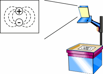
Bits of material suspended in oil align with an applied electric field. Several pole arrangements are shown. |
||
|
5B20.10 |
ELECTRIC FIELDS AND POTENTIAL |
|
|
Gauss' Law |
||
Faraday's Ice Pail |
||
|
|
||
|
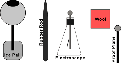
Charge the sphere several times by rubbing a charged rod on its surface. Touch the proof plane to the outside of the sphere and then to the electroscope. The electroscope charges, indicating there is a charge on the outside of the sphere. Repeat the same test on the inside of the sphere. The electroscope does not charge. |
||
|
5B20.35 |
ELECTRIC FIELDS AND POTENTIAL |
|
|
Gauss' Law |
||
Radio in a Cage |
||
|
|
||
|
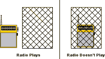
Turn on the light and the radio. You should hear static that the radio picks up from the fluorescent light source. Place the Faraday cage over the radio and you hear nothing. |
||
|
5B30.35 |
ELECTRIC FIELDS AND POTENTIAL |
|
|
Electrostatic Potential |
||
Point and Ball with Van de Graaff |
||
|
|
||
|
Hold a ball close to a VDG and then bring a point close. |
||
|
5C10.20 |
CAPACITANCE |
|
|
Capacitors |
||
Parallel Plate Capacitor |
||
|
|
||
|
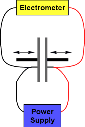
Change the spacing of a charged parallel plate capacitor while it is attached to an electroscope. |
||
|
5C20.10 |
CAPACITANCE |
|
|
Dielectrics |
||
Capacitor with Dielectrics |
||
|
|
||
|
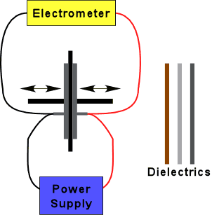
Place a dielectric between the plates and push the plated against the dielectric. Turn on the power supply to charge the plates. Disconnect ground lead BEFORE turning the supply off. Slide the dielectric out of he plates and observe how the electroscope changes. Insert other dielectrics. |
||
|
5C30.20 |
CAPACITANCE |
|
|
Energy Stored in a Capacitor |
||
Short a Capacitor |
||
|
|
||
|
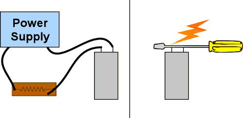
Turn on the power supply to charge the 5600 microfarad capacitor through the power resistor. Remove the leads from the capacitor without touching the binding posts. Short the posts with the shaft of a screw driver (not the tip). |
||
|
5C30.30 |
CAPACITANCE |
|
|
Energy Stored in a Capacitor |
||
Light the Bulb |
||
|
|
||
|
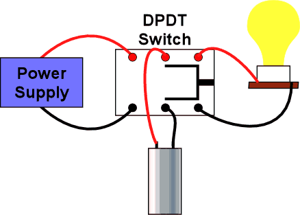
Turn on the power supply to charge the capacitor through the power resistor. Turn off the power and disconnect the power supply. To discharge the capacitor, connect to the light bulb only. Do not short the capacitor. The 60W bulb lights for about 3 seconds. A 7.5 W bulb lights for about 20 seconds. |
||
|
5D10.40 |
RESISTANCE |
|
|
Resistance Characteristics |
||
Resistance Model |
||
|
|
||
|
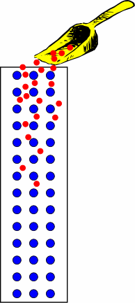
Ball bearings are rolled down an inclined bed of nail to simulate current flow in a wire. |
||
|
5D20.10 |
RESISTANCE |
|
|
Resistivity and Temperature |
||
Wire Coil in LN2 |
||
|
|
||
|
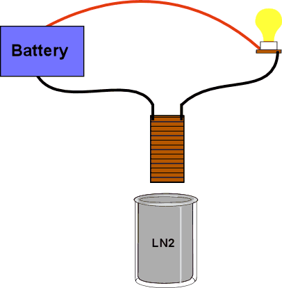
Set up as shown. Place the coil into the LN2. Watch the light bulb get brighter as the coil cools. |
||
|
5D20.60 |
RESISTANCE |
|
|
Resistivity and Temperature |
||
Conduction in Glass |
||
|
|
||
|
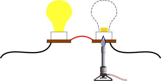
A light bulb is smashed with a mallet and the filament is cut off. Then, the glass stem is heated with a blow torch. |
||
|
5D40.10 |
RESISTANCE |
|
|
Conduction in Gases |
||
Jacob's Ladder |
||
|
|
||
|
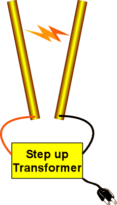
This is a step up transformer. CAUTION: LETHAL VOLTAGE Turn on the power and the discharge will travel up the wires. The distance between the wires is the critical adjustment. The wires should not be moving. This does not work will on humid days. Unplug after use so that students don't inadvertently play with it. |
||
|
5E40.25 |
ELECTROMOTIVE FORCE AND CURRENT |
|
|
Cells and Batteries |
||
Lemon
|
||
|
|
||
|
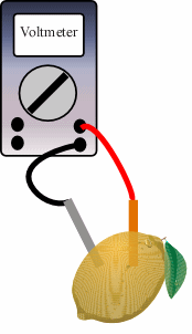
Copper and Zinc electrodes in a lemon are connected to a digital meter. |
||
|
5E50.10 |
EMF AND CURRENT |
|
|
Thermoelectricity |
||
Thermocouple |
||
|
|
||
|
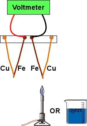
A voltmeter is connected to the iron wires of two copper-iron wire junctions hanging from a stand. Light the Bunsen burner and heat one of the junctions, watching the voltmeter. You can also immerse a junction in ice. |
||
|
5F10.10 |
DC CIRCUITS |
|
|
Ohm's Law |
||
Ohm's Law |
||
|
|
||
|
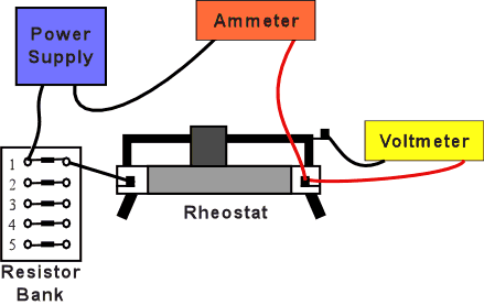
Digital meters measure the current and the voltage in a simple circuit of a battery and resistor. The rheostat is adjusted so that the meters read the same, differing only by a factor of 1000. The battery pack contains six 1.5 volt batteries in series. Change the number of batteries in the circuit OR change the resistance and observe that the meters change proportionally. |
||
|
5F15.35 |
DC CIRCUITS |
|
|
Power and Energy |
||
Fuse with Increasing Load |
||
|
|
||
|
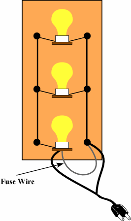
A fuse wire will eventually fail when the load on the circuit is increased. |
||
|
5F20.10 |
DC CIRCUITS |
|
|
Circuit Analysis |
||
Kirchhoff's Voltage Law |
||
|
|
||
|
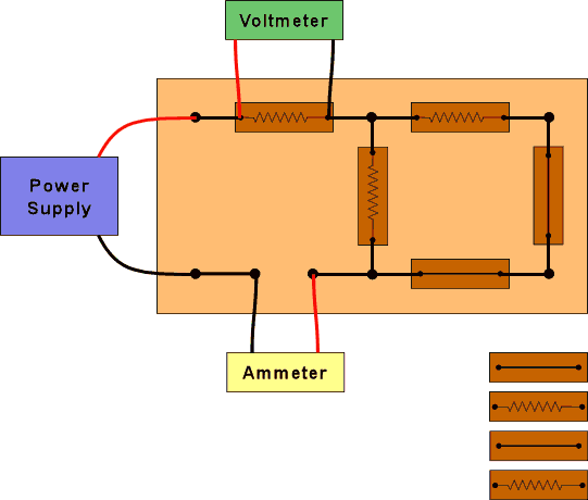
Measure the voltage at different places in the circuit and show that the sum is zero. There are many possible combinations of components. |
||
|
5F20.50 |
DC CIRCUITS |
|
|
Circuit Analysis |
||
Series and Parallel Circuits |
||
|
|
||
|
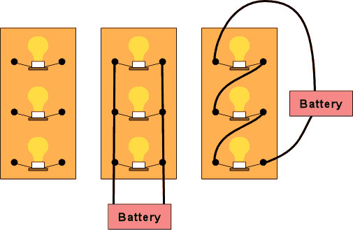
If the combined series and parallel boards are confusing, try the separate boards. |
||
|
5F30.10 |
DC CIRCUITS |
|
|
RC Circuits |
||
Capacitor and Light Bulb |
||
|
|
||
|
A 5600 microfarad capacitor, a light bulb, and a 120 V dc supply in series show a long time constant where the bulb dims as the capacitor charges. |
||
|
5G10.20 |
MAGNETIC MATERIALS |
|
|
Magnets |
||
Break a Magnet |
||
|
|
||
|
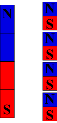
A broken magnet still exhibits north and south poles.
|
||
|
5G30.10 |
MAGNETIC MATERIALS |
|
|
Paramagnetism and Diamagnetism |
||
Paramagnetism and Diamagnetism |
||
|
|
||
|
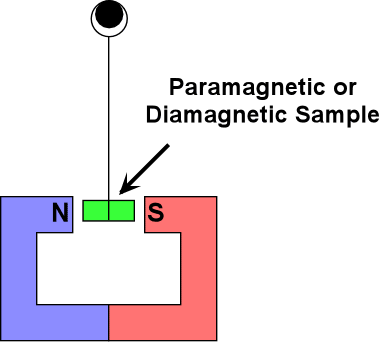
Paramagnetic and diamagnetic crystals are inserted between the poles of a large magnet or electromagnet. |
||
|
5G50.10 |
MAGNETIC MATERIALS |
|
|
Temperature and Magnetism |
||
Curie Point |
||
|
|
||
|
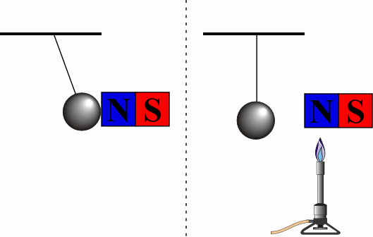
Iron under magnetic attraction is heated until it falls away. Upon cooling it is again attracted. |
||
|
5G50.50 |
MAGNETIC MATERIALS |
|
|
Temperature and Magnetism |
||
Meissner Effect |
||
|
|
||
|
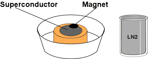
Place a magnet on warm superconducting disk to show how nothing happens, then remove. Add LN2 to the Styrofoam container holding the super conducting disk. When the boiling stops, the disk is cold. Use the plastic tweezers to place one of the magnets on the disk. The magnet will float above the disk. |
||
|
5H10.20 |
MAGNETIC FIELDS AND FORCES |
|
|
Magnetic Fields |
||
Oersted's Effect |
||
|
|
||
|
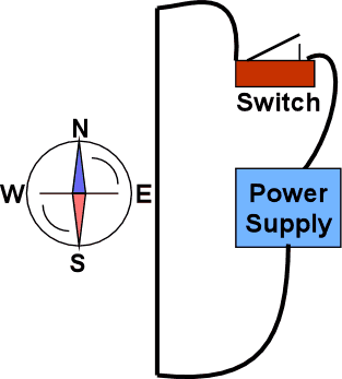
Turn the compass needle so it is approximately parallel to the wire. Close the switch to send the current through the wire for about 5-10 sec. The compass will align itself with the magnetic field. |
||
|
5H10.30 |
MAGNETIC FIELDS AND FORCES |
|
|
Magnetic Fields |
||
Magnet and Iron Filings |
||
|
|
||
|
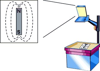
Sprinkle iron filings on the Plexiglas plate. Tap the Plexiglas to encourage alignment. |
||
|
5H15.10 |
MAGNETIC FIELDS AND FORCES |
|
|
Fields and Currents |
||
Magnetic Field Around Wire |
||
|
|
||
|
Sprinkle iron filings on the Plexiglas. Hold down the switch briefly connecting the bottom while tapping the Plexiglas to encourage alignment. |
||
|
5H15.40 |
MAGNETIC FIELDS AND FORCES |
|
|
Fields and Currents |
||
Solenoid and Iron Filings |
||
|
|
||
|
Sprinkle iron filings on the Plexiglas. Hold down the tap switch briefly connecting the bottom while tapping the Plexiglas to encourage alignment. |
||
|
5H20.10 |
MAGNETIC FIELDS AND FORCES |
|
|
Forces on Magnets |
||
Magnets and Pivot |
||
|
|
||
|
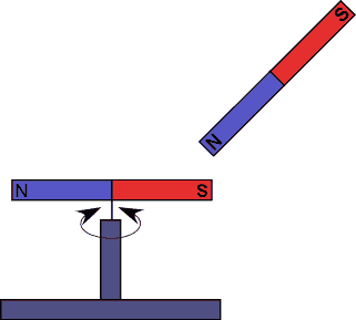
One magnet is centered on a pivot. Hold one end of the second magnet near one end of the magnet on the pivot. Repeat with the opposite end. |
||
|
5H30.10 |
MAGNETIC FIELDS AND FORCES |
|
|
Force on Moving Charges |
||
Cathode Ray Tube |
||
|
|
||
|
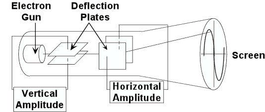
Plug in the cathode ray tube. Deflect the beam of the CRT by holding a permanent magnet near the edge of the tube. If the beam disappears, you are holding the magnet too close. OR, deflect the beam by attaching a battery to the binding posts and adjusting the variable control knob. OR connect the battery directly to the deflection plate terminals. |
||
|
5H40.10 |
MAGNETIC FIELDS AND FORCES |
|
|
Forces on Current in Wires |
||
Parallel Wires |
||
|
|
||
|
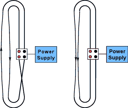
Two insulated wires hang from a frame. Turn on the switch. Wires will attract or repel each other. Turn off the switch and reverse the leads in the binding posts. Turn the switch on. Wires will repel or attract each other. |
||
|
5H40.15 |
MAGNETIC FIELDS AND FORCES |
|
|
Forces on Current in Wires |
||
Interacting Coils |
||
|
|
||
|
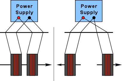
Hang two coils from a support rod. Connect the DC power supply so that the current is in the same direction in both coils and watch them attract. Connect the DC power supply in opposite directions in the coils and watch them repel. A good storage battery can be used instead of the power supply. |
||
|
5H40.30 |
MAGNETIC FIELDS AND FORCES |
|
|
Forces on Current in Wires |
||
Jumping Wire |
||
|
|
||
|
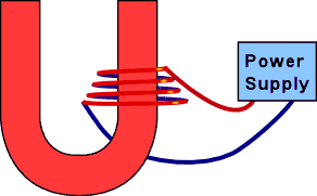
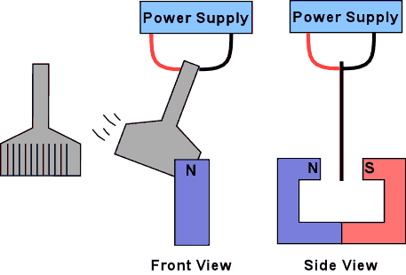
A long wire is coiled around one pole of a permanent magnet. Close the switch. The wire collapses into the magnet. Turn the coil over and repeat. The wire "jumps" out of the magnet. |
||
|
5H50.10 |
MAGNETIC FIELDS AND FORCES |
|
|
Torques on Coils |
||
Model Galvanometer |
||
|
|
||
|
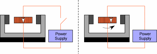
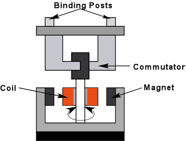
A crude galvanometer with a large coil and magnet demonstrates the essentials. |
||
|
5J20.10 |
INDUCTANCE |
|
|
LR Circuits |
||
LR Time Constant on Scope |
||
|
|
||
|
A plug in circuit board with a make before break switch for showing slow RL time constants on the oscilloscope. |
||
|
5J20.20 |
INDUCTANCE |
|
|
LR Circuits |
||
Series or Parallel Lamps w/Inductor |
||
|
|
||
|
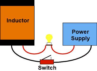
Two lamps are used to indicate voltage across and current through a large electromagnet. Do this with the iron core in and then with the iron core removed. |
||
|
5K10.20 |
ELECTROMAGNETIC INDUCTION |
|
|
Inducted Current and Forces |
||
Induction Coil and Magnet |
||
|
|
||
|
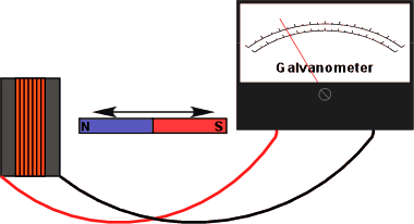
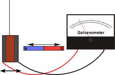
Move the magnet in and out of the coil connected to the galvanometer. |
||
|
5K10.30 |
ELECTROMAGNETIC INDUCTION |
|
|
Inducted Current and Forces |
||
Mutual Induction
Coils with
|
||
|
|
||
|
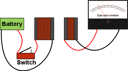
Two coils face each other, one attached to a galvanometer, the other to a battery and tap switch. Coupling can be increased with various cores. Aluminum, laminated iron, and other solid iron cores are available. |
||
|
5K20.10 |
ELECTROMAGNETIC INDUCTION |
|
|
Eddy Currents |
||
Pendulum in Big Electromagnet |
||
|
|
||
|
Show that a solid copper plate swings between the poles of the electromagnet when the power is off. Turn on the power. Displace the pendulum and let it swing. It stops dead between the poles. Repeat with the slotted plate, ring and slit ring. Cannot leave the power on. |
||
|
5K20.25 |
ELECTROMAGNETIC INDUCTION |
|
|
Eddy Currents |
||
Magnets and Tubes |
||
|
|
||
|
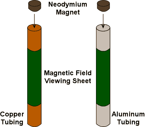
Drop magnets simultaneously down the copper and stainless steel tube. It takes approximately 3 seconds for the magnet to fall through the three foot copper tube. Dummy magnets are also available. Aluminum tubes will also show damping. |
||
|
5K20.26 |
ELECTROMAGNETIC INDUCTION |
|
|
Eddy Currents |
||
Faraday Repulsion Coil |
||
|
|
||
|
A magnet is inserted and withdrawn from a solid and split ring on a bifilar suspension. It is possible to "pump" the solid ring. |
||
|
5K30.20 |
ELECTROMAGNETIC INDUCTION |
|
|
Transformers |
||
Dissectible Transformer |
||
|
|
||
|
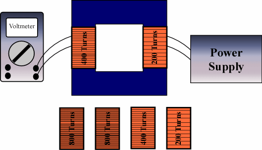
Voltages can be shown on the primary and secondary coils of a dissectible transformer. |
||
|
5K40.40 |
ELECTROMAGNETIC INDUCTION |
|
|
Motors and Generators |
||
Motor / Generator |
||
|
|
||
|
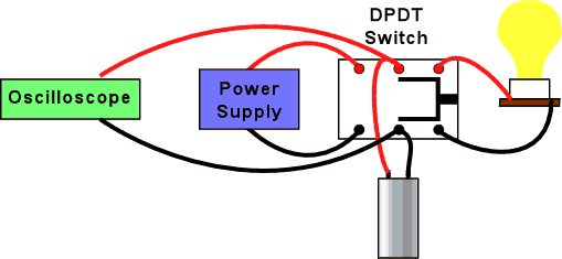
Use the double throw switch to connect the battery to the motor. The 500 gram mass will rise. Switch to neutral and let the mass fall halfway down to build up speed. Switch to light bulb and bulb will light. |
||
|
5L20.20 |
AC CIRCUITS |
|
|
RLC Circuits - AC |
||
RLC Resonance |
||
|
|
||
|
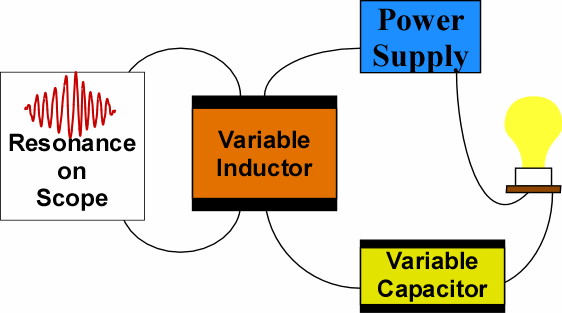
The light bulb in a RLC circuit glows when the inductor core is moved through resonance. Also, RLC resonance shown on an oscilloscope. |
||
|
5N10.80 |
ELECTROMAGNETIC RADIATION |
|
|
Transmission Lines and Antennas |
||
EM Vectors |
||
|
|
||
|
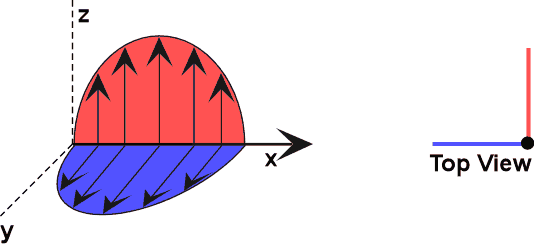
A dynamic model for demonstrating electric and magnetic vectors in an electromagnetic field. |
||
|
5N20.10 |
ELECTROMAGNETIC RADIATION |
|
|
Tesla Coil |
||
Induction Coil |
||
|
|
||
|
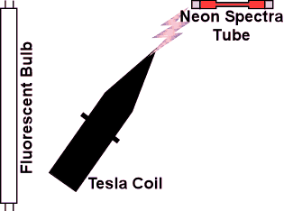
Turn on the Tesla coil. Take the spectra tube and hold it within 2 feet of the Tesla coil. Vary the distance. Do the same thing with the fluorescent tube. Using the grounding wire on the end of the tube can help avoid unpleasant shocks. Discuss shocks vs. burns and high frequency AC. |
||
|
5N30.10 |
ELECTROMAGNETIC RADIATION |
|
|
Electromagnetic Spectrum |
||
Projected Spectrum w/Prism |
||
|
|
||
|
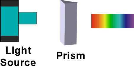
White light is projected through a high dispersion prism and onto a screen. |
||
